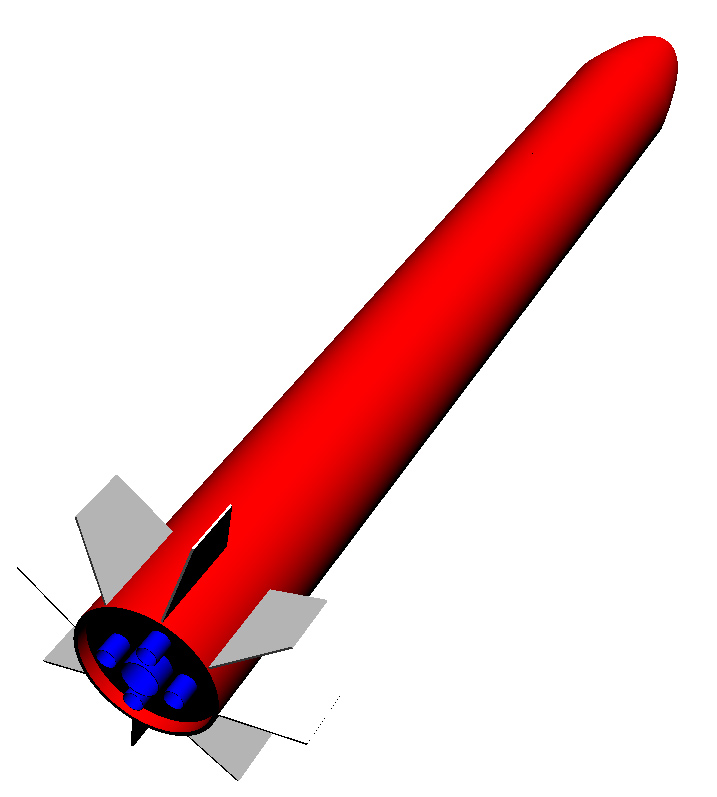
"Heavy Metal Thunder" Build"Heavy Metal Thunder" (HMT) is a rocket I'm scratch-building using 8" concrete tube forms. It's going to be about 8 3/4" inches in diameter and about 5 1/2' tall. The rocket will feature eight clear Lexan fins.
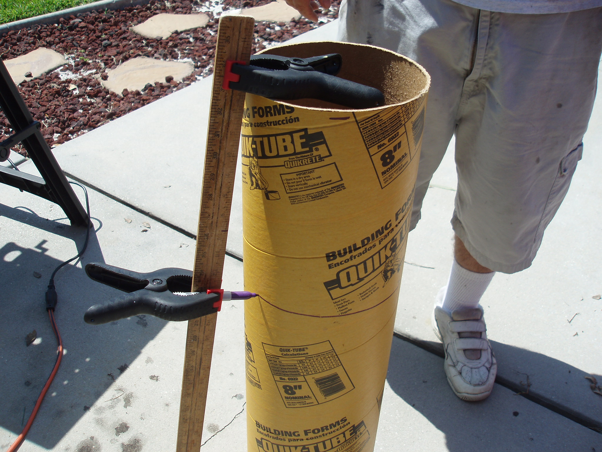
The rocket is designed to fly on a J motor or a cluster of five motors. In addition to being my "Level 2" certification rocket, HMT is designed to test some of the ideas for the 1/48th scale Saturn V I'm building and to help me develop the skills I will need for the Saturn V. The first thing I did was to cut the tubes. I made a simple jig from a couple of clamps, a yardstick, and a Sharpie pen and used the contraption to draw lines around the tubes.
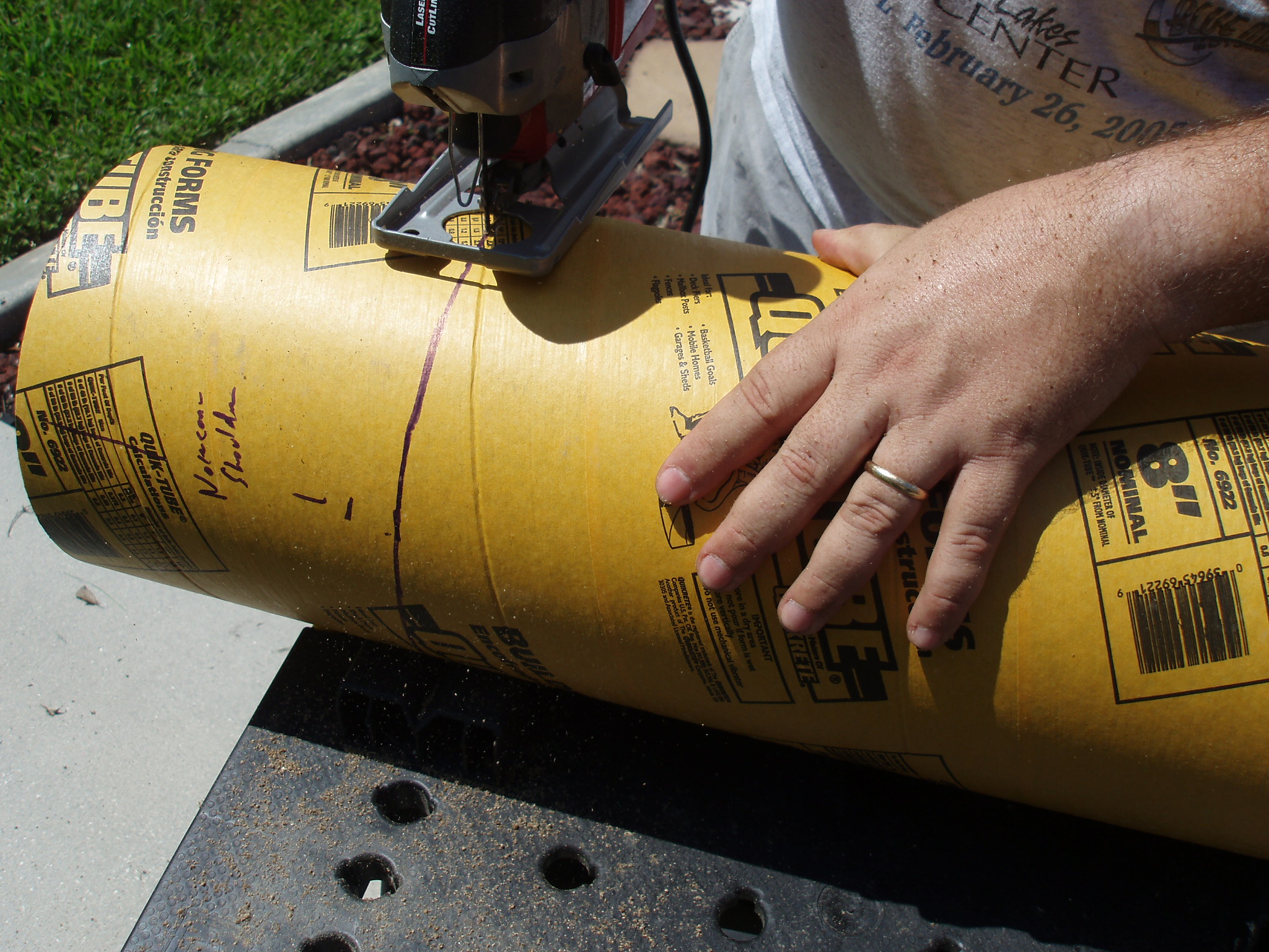
Then I used a jig saw to cut the tubes along the lines.
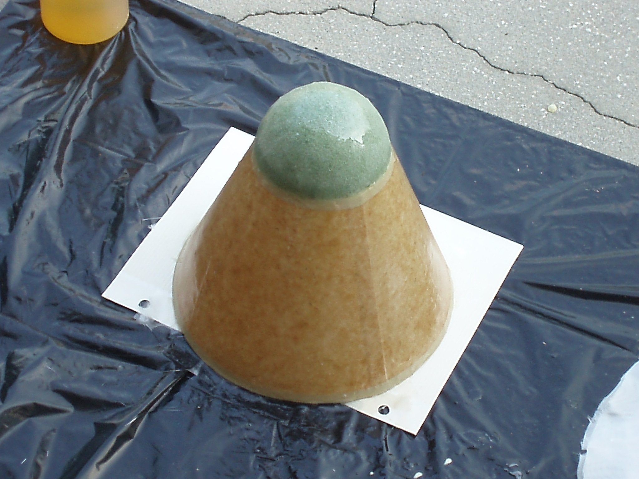
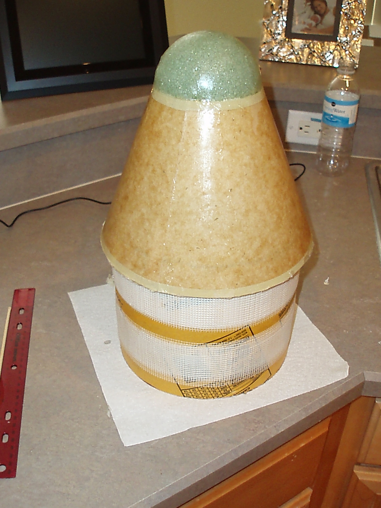
The I cut out a bulkhead for the bottom of the nose cone. I made a jig from a piece of 4" x 1/4" poplar. A piece of 1/4" plywood is screwed to one end of the jig. The other end is clamped on the tray of my drill press. I put a Dremel cutting bit in the drill press. I used this to cut a circle slightly larger than the desired size. Then I removed the circle and used a Dremel circle cutter with my Dremel tool to cut the circle down to the desired size. I glued the bulkhead to a circle of foam, added a big screw eye and glued the bulkhead and foam into the tube I cut for the shoulder of the nose cone. Next, I crafted the rest of the nose cone using a lampshade as a form and half a foam ball for the tip of the nose cone.
I covered the whole thing with a few layers of fiber glass. Then filled it most of the way with expanding foam.
Finally, I glued the nose assembly to the shoulder and filled it the rest of the way with foam.
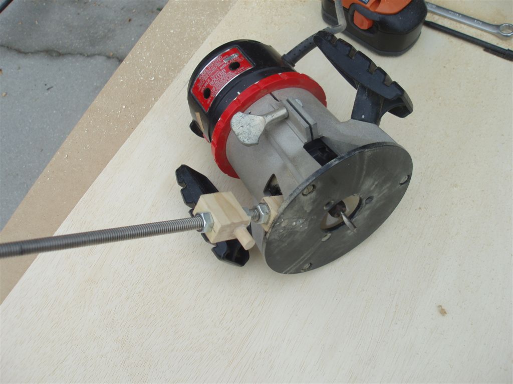
Later, the entire assembly will be expoxied into the upper body tube and the edge of the nose cone will be cut and sanded to the diameter of the body tube. October 27, 2007: I created a tool for cutting circles based on the jig described at http://www.woodworkingtips.com/etips/2004/10/08/sn/.
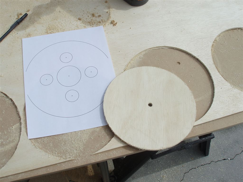
The jig worked well and I was able to quickly cut out a few centering rings.
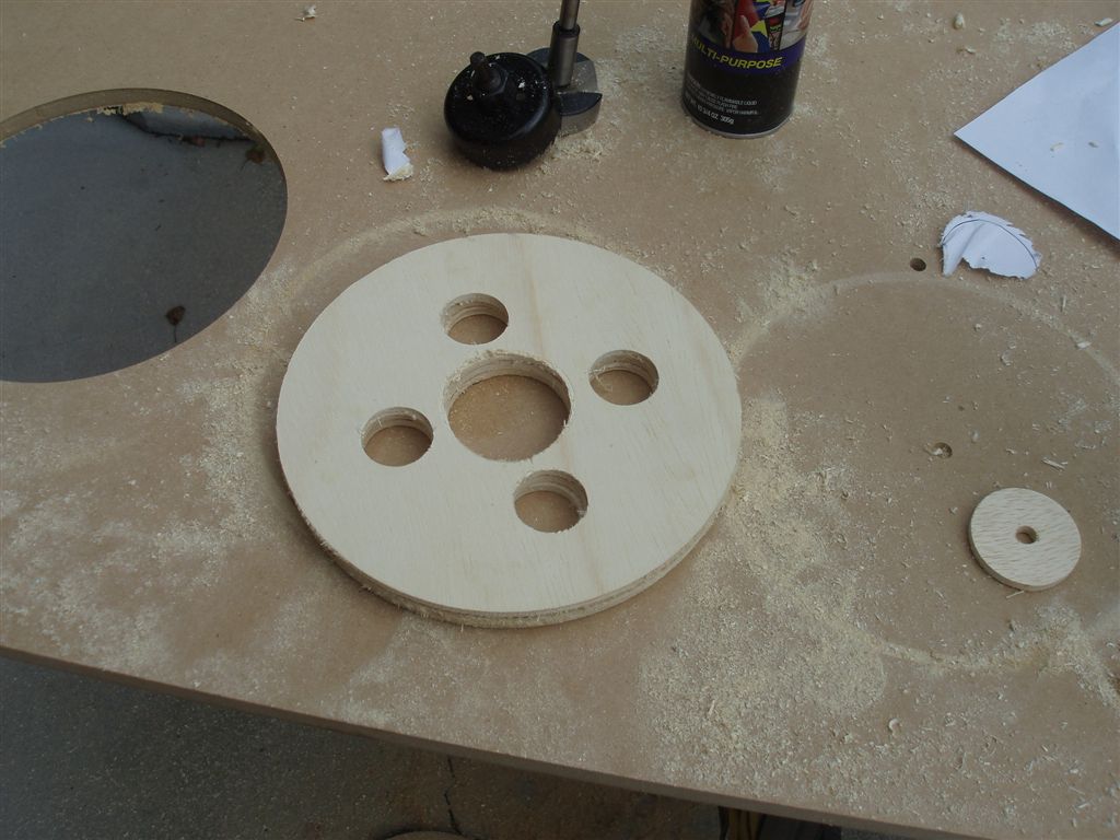
I used Payload Bay's Center Ring/Motor Mount Tool to create a template for the motor mount rings. Then I used a hole saw to cut out the center for a 54mm motor tube and a wide drill bit to make holes for the 29mm motor tubes.
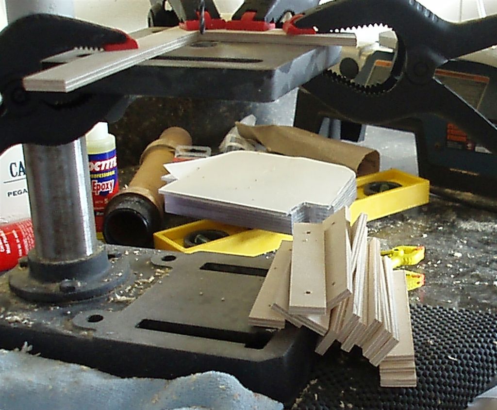
November 2, 2007: I cut all eight fins out of Lexan. First I cut eight square pieces slightly larger than the fins. I glued all eight pieces into a single stack using a light mist of 3M Super 77 spray adhesive. I cut out the fins using a jig saw then used my new Belt/Disc Sander to ensure the fins were all the same size/shape and to round the corners of the fins.
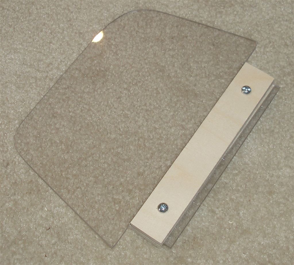
I cut out 16 fin "braces" from strips of wood and drilled holes for screws through them. I attached these to the fins.
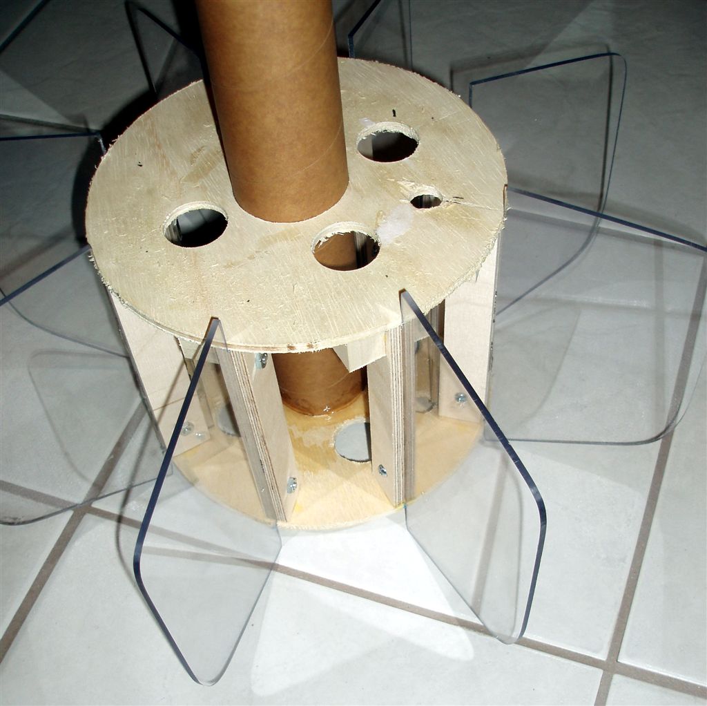
Using blocks of wood as additional supports, I glued the fin assemblies to two motor mount rings to form the fin can.
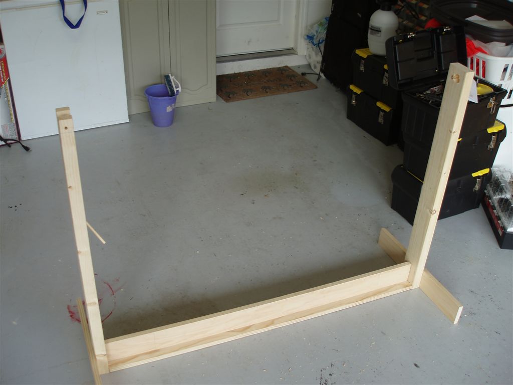
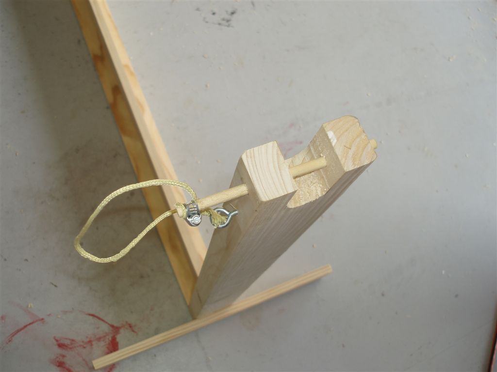
November 23, 2007: I spent the day shopping for wood and using it to build a stand for fiberglassing the tubes for the rocket. I based the design on the one described in on the web page Airframe Tube Fiberglassing Rotisserie Stand. Until I find a cheap rotisserie motor, however, mine will require manual rotating of the tube.
The frame supports a 3/4" wooden rod (a gardening tool handle). I'll slide pieces of foam over the wooden rod to use as a mandrel to hold the tube on the rod then attach the rod to the frame.
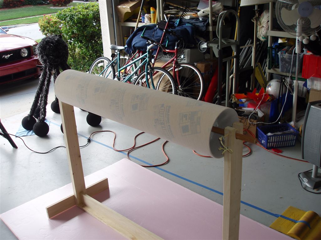
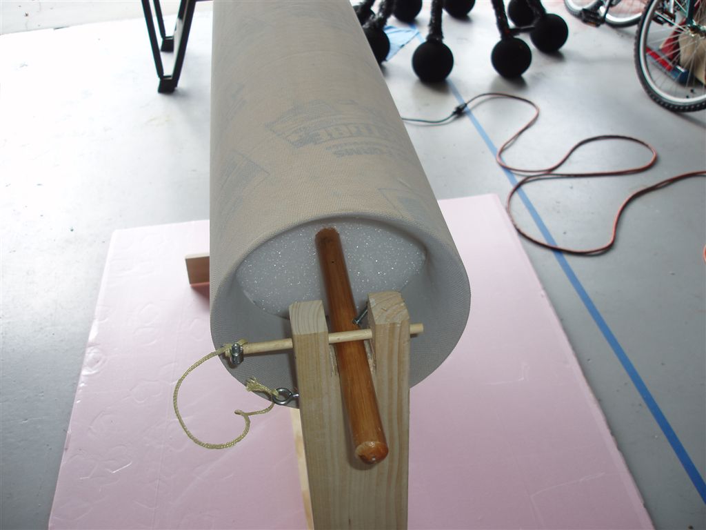
November 24, 2007: The fiberglassing stand worked very well.
I pulled a cloth sleeve over the main body tube and held it in place with the foam discs that also held the tube on the rod.
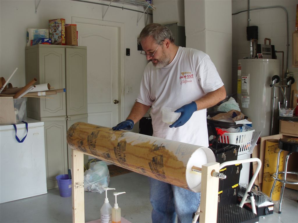
I covered the tube with epoxy resin and rotated it periodically as it dried.
The tube came out pretty nice. I have one more tube to cover with fiberglass then I'll seal and sand both of the tubes. December 8, 2007: I used one part epoxy to about three parts microballons to make a filler for the body tube. This creates a sandable coating to fill in the weave of the fiberglass I applied to the tube.
I automated the fiberglassing stand by adding a bracket to hold my cordless drill. This turns the tube while the epoxy dries so that it is smooth and even.
December 28, 2007: I've spent the past couple of days sanding and priming and sanding and priming the body tubes and nosecone. With all the mess, I didn't try taking pictures. I'll try to get some tomorrow as I finish priming the rocket and start painting it.
I also built a "pod" for one of the altimeters. The idea is that the altimeters will each reside in one of these pods for easy access and to make them re-usable in the Saturn V's electronics bay. I started by cutting a piece of 29mm motor mount tube to length. Then I cut a notch out of the side of it. I mounted the MAWD altimeter to a small piece of wood and glued it into the tube. I added a few more pieces of wood to brace the tube (leaving space for a 9v battery). Then I cut a three-inch long piece of 38mm motor tube and a piece the same length as a 38mm motor's thrust ring (about .4"). I cut a slit down the length of the 3" tube to reduce its diameter so it fit inside the smaller tube. I used a wrap of masking tape to make the new diameter a little less than the inside diameter of a 38mm motor mount tube. I glued the 3" tube inside the short tube. Then I glued this assembly to one end of the 29mm tube containing the altimeter. This creates an assembly that can slide into a 38mm motor tube and secured in the same way a motor would be retained. [Posted: 2007-06-23 | Updated: 2007-12-28] |